Beamforming and Conformal Antenna Arrays
Published:
In order to predict the performance envelope of an array, the effects of beamforming the aperture need to be taken into account. The array is modelled using electric current sources to replicate the individual elements and "Equal Gain Combining" to form the beam efficiently in along the desired directions.
In the last post, I introduced the potential of modelling an array as a mesh of electric current sources but stopped short of introducing the mathematics required to "form" the beam properly in the required direction. 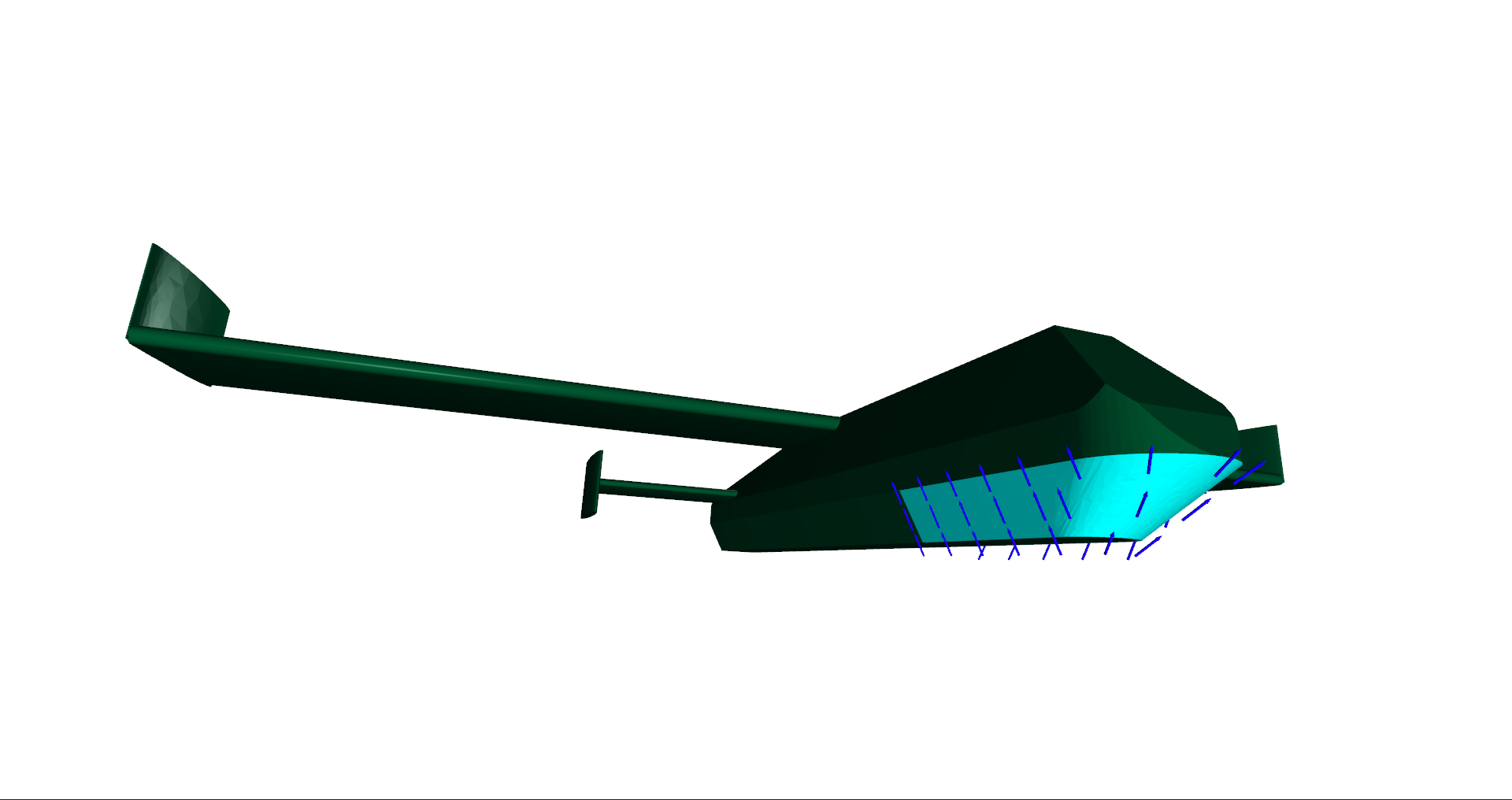 The antenna mesh used is shown here by representing the electric current sources as blue arrows across the surface of the conformal antenna array.
The beamforming algorithm used here is "Equal Gain Combining". I prefer this to coherent wavefront beamsteering because when the patterns are fully "known" it is simple to implement, as the phase weights for each element are calculated by polling the farfield phase in the desired direction, then applying it’s inverse to that element. If the directivity is then recorded in the desired direction then a map of the beam total directivity envelope can be constructed as in the figure below. The scale used is also uses on all the included point cloud pattern plots.
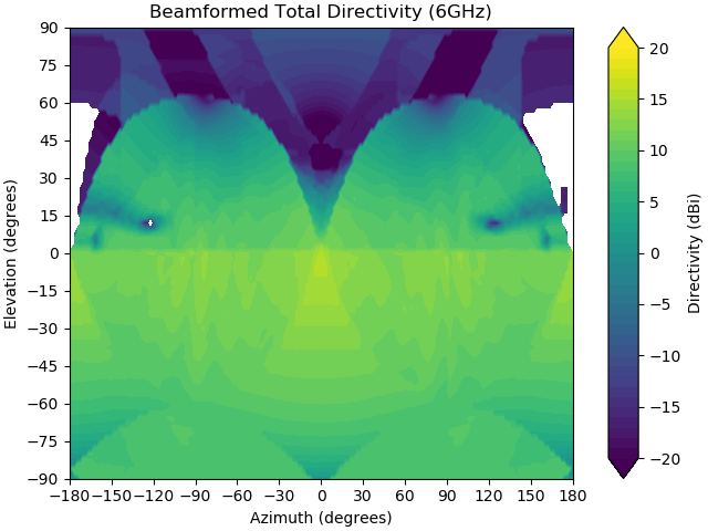
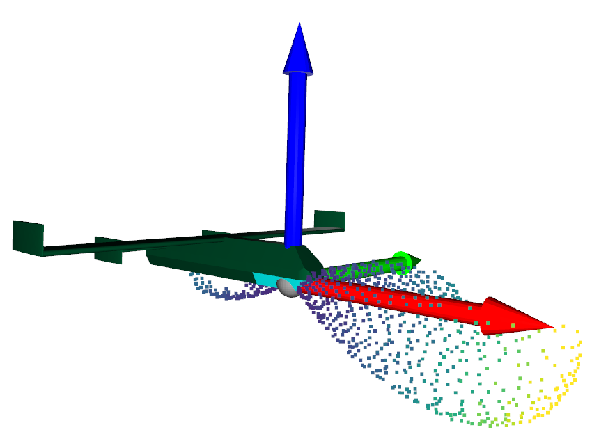
The maximum achieved directivity across all polled command angles is 16dBi, this is interesting as the eagle eyed reader will note that the shared scale for the directivity map and beamformed cloud pattern plots has a larger upper limit. This is because the maximum directivity will not always be in the desired direction. This is easy to imagine when the desired direction is blocked by some object, such as the fuselage in this figure.
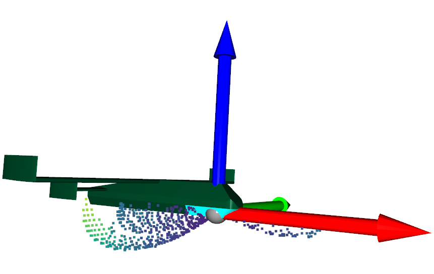
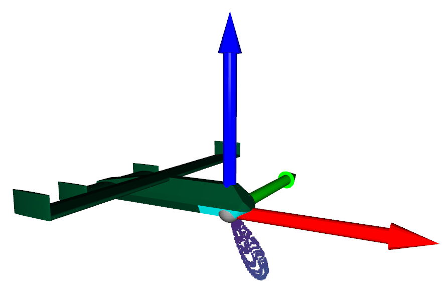
It is somewhat harder to see when the beam is formed towards Azimuth of 0 degrees, and Elevation of 0 degrees. But if the reader looks along the x axis (red arrow), then it becomes easier to see that the pattern maxima is not quite aligned with this direction.
One of the major consequences of array polarization is it’s influence on the array steerability. Because Z axis aligned current sources were chosen for this example, they steer well in the azimuth direction, but increasing elevation angles away from the array normal vector cause the achievable directivity to drop quickly. As can be seen by steering the beam to first Elevation of -30 degrees, in the first figure, and -60 degrees in the second.

